Close


Download
By using the toggle link principle toggle clamps offer decisive advantages:
The clamping arm retracts to such an extent that the workpiece can be loaded and unloaded completely unobstructed.
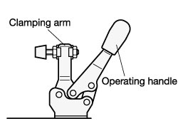
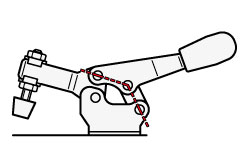
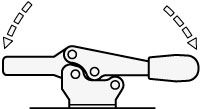
Even the slightest forward movement of the operating handle brings the clamping arm with the contact pad over the workpiece.
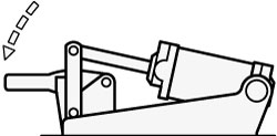
As can be seen from the sketch, the position of the toggle links will lead to a multiple of the input force applied to the operating handle.
In this position the Toggle clamp is not yet fully engaged and any counter force will open it.
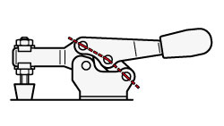
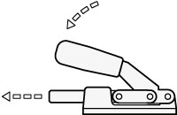
In this position all three pivots are perfectly aligned yielding the maximum clamping force Fs (dead centre point).
The clamping force Fs exerted on the workpiece is mainly dependent on the following criteria:
- the input force which is applied to the operating handle,
- the position of the clamping bolt on the clamping lever.
The clamping force Fs can be altered by re-adjusting the position of the clamping bolt. The clamping force increases if the entire contact area of the bolt arrives on the workpiece prior to the toggle linkage reaching dead centre point. This effect is illustrated clearly when using an elastic clamping pad.
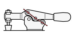
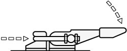
In this position the toggle linkage has arrived in the over-centre lock position and the operating lever has reached a firm stop and is thus prevented from opening until it is released by the operator.
The force which the clamp is capable of withstanding in this over-centre lock position without suffering permanent deformation is known as holding force FH. The holding force has a characteristic value (co-efficient) for toggle clamps and this value is mainly dependent on:
- the size (dimensions, geometry) of the toggle clamp,
- the position of the clamping bolt on the clamping arm.
On the standards sheets all clamps are shown in their clamping position.
All references to force are given in N (Newton).
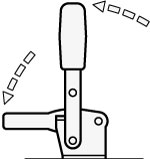
Vertical acting toggle clamps
Lever and clamping bar move in the same direction.
In the clamped position the operating handle is in vertical position.
For applications where substantial forces and many tightening cycles occur, „Longlife“ versions are available.
Horizontal acting toggle clamps
Lever and clamping bar move in opposite direction.
In the clamped position the operating handle is in horizontal position (flat version).
Push-pull type toggle clamps
On these clamps the swinging movement of the operating handle is converted into an axial movement to push or pull the plunger.
With the exception of two versions (GN 841 see page 1588) , they lock at the end of their stroke in both directions. For this reason they lend themselves for push or pull operations.
Latch type toggle clamps
On these clamps the swinging movement of the operating handle is converted into an axial movement to pull the hook.
Latch clamps are available with and without locking mechanism.
Pneumatic toggle clamps
These toggle clamps combine the advantages of clamping by the toggle principle (clamp remains in the clamping position even in the event of air pressure loss!) with the advantages offered by pneumatics i.e.:
Latch clamps are available with and without locking mechanism.
- constant clamping force Fs independent of the operator,
- several clamps can be operated simultaneously,
- pneumatic toggle clamps can be energised from various operating points (remote control, co-ordinated and controlled by other machines),
- some variants are available with an air cylinder which allows control via a proximity switch, to give an electrical impulse when the clamp has reached a specific position within its clamping cycle.