Close


Download
5.6 Choosing the wheel
Each of the parameters and operating characteristics outlined in the previous paragraphs is used in one of the three steps involved in choosing the wheel.
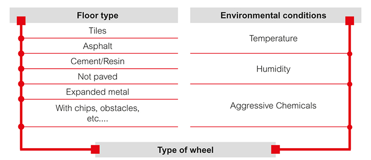
Step 1
The type of wheel suitable for the floor and operating environment is identified in step 1. The following graph summarizes the factors that influence the choosing of the type of wheel; type of wheel means:
- materials that form the covering and the wheel centre body;
- type of anchorage between covering and wheel centre body;
- rolling actions.
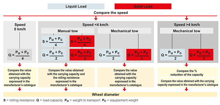
Step two
The load capacity, static load and smoothness values required by the specific application and needed to determine the wheel diameter are calculated in step two.
One of the most important parts of this step is an analysis of the load that the wheel must support. The following diagram indicates what calculations to perform and what values to consider depending on the various operating conditions. These aspects must always be indicated (magnitude and nature of the load and speed), while ensuring that all the values determined are not higher than the rated values indicated in the manufacturer's catalogue. If the evaluation of various aspects generates different data with reference to the same wheel characteristic, the final choice must be made based on the most conservative condition.
Step three
The correct castor is chosen in the third step. The step can be divided into two separate parts:
- Choosing fixed or swivel brackets, depending on manoeuvrability and directionality needs;
- Checking the compatibility between dynamic load capacity and rated dynamic load capacity of the wheel and bracket.
The following table summarizes some general indications for choosing the right wheels according to the application's features.
| Selection parameters | Value range | RE.FF | RE.F1 | RE.F2 | RE.F5 | RE.F5-ESD |
| Load capacity | Light load, up to 250 kg | ● | ● | ● | ● | ● |
| Medium load, up to 750 kg | ● | ❐ | ● | ● | ● | |
| Heavy load, more than 750 kg | ▲ | ▲ | ❐ | ● | ❐ | |
| Rolling resistance | < 125 kg | ● | ● | ● | ● | ● |
| > 125 kg | ● | ● | ● | ● | ● | |
| Flooring | Tiles | ● | ● | ● | ● | ● |
| Asphalt | ❐ | ❐ | ● | ❐ | ❐ | |
| Cement - Resin | ● | ● | ● | ● | ● | |
| Not paved | ❐ | ❐ | ● | ❐ | ❐ | |
| Expanded metal | ▲ | ❐ | ● | ❐ | ❐ | |
| With chips, obstacles, etc. | ▲ | ❐ | ❐ | ❐ | ❐ | |
| Environmental chemical conditions | In the presence of chemicals | ● | ● | ❐ | ❐ | ❐ |
| Temperature | -40° / -20° | ▲ | ▲ | ▲ | ▲ | ▲ |
| -20° / +80° | ● | ● | ● | ● | ● | |
| +80° / +120° | ▲ | ▲ | ❐ | ❐ | ▲ | |
| > 120° | ▲ | ▲ | ▲ | ▲ | ▲ | |
| Means of traction | Manual (speed ≤ 4 Km/h) | ● | ● | ● | ● | ● |
| Mechanical (speed ≤ 16 Km/h) | ▲ | ▲ | ● | ● | ● |
| Selection parameters | Value range | RE.F4 | RE.F8 | RE.F7 | RE.G1 | RE.E2 | RE.E3 | RE.G2 | RE.G5 |
| Load capacity | Light load, up to 250 kg | ● | ● | ● | ● | ● | ● | ● | ● |
| Medium load, up to 750 kg | ● | ● | ▲ | ▲ | ▲ | ▲ | ● | ● | |
| Heavy load, more than 750 kg | ● | ● | ▲ | ▲ | ▲ | ▲ | ▲ | ● | |
| Rolling resistance | < 125 kg | ● | ● | ● | ● | ● | ● | ● | ● |
| > 125 kg | ● | ● | ● | ▲ | ▲ | ▲ | ● | ● | |
| Flooring | Tiles | ● | ❐ | ❐ | ● | ● | ● | ● | ● |
| Asphalt | ❐ | ▲ | ▲ | ❐ | ● | ● | ● | ❐ | |
| Cement - Resin | ● | ● | ● | ● | ● | ● | ● | ● | |
| Not paved | ❐ | ❐ | ❐ | ❐ | ● | ● | ● | ❐ | |
| Expanded metal | ❐ | ▲ | ▲ | ▲ | ● | ● | ● | ❐ | |
| With chips, obstacles, etc. | ❐ | ▲ | ▲ | ▲ | ● | ● | ● | ❐ | |
| Environmental chemical conditions | In the presence of chemicals | ❐ | ● | ● | ● | ▲ | ▲ | ❐ | ❐ |
| Temperature | -40° / -20° | ▲ | ❐ | ❐ | ▲ | ▲ | ❐ | ❐ | ▲ |
| -20° / +80° | ● | ● | ● | ● | ● | ● | ● | ● | |
| +80° / +120° | ❐ | ❐ | ● | ▲ | ▲ | ❐ | ❐ | ❐ | |
| > 120° | ▲ | ▲ | ● | ▲ | ▲ | ▲ | ▲ | ▲ | |
| Means of traction | Manual (speed ≤ 4 Km/h) | ● | ● | ● | ● | ● | ● | ● | ● |
| Mechanical (speed ≤ 16 Km/h) | ● | ▲ | ▲ | ▲ | ▲ | ▲ | ❐ | ❐ |
● Reccommended ❐ Tolerated ▲ Not recommended
-
Generals
-
1. Plastic materials
- 1.1 Mechanical strength
- 1.2 Thermal resistance
- 1.3 Strength and surface hardness
- 1.4 Resistance to chemical agents
- 1.5 Resistance to atmospheric agents and uv rays
- 1.6 Flame resistance
- 1.7 Electrical properties
- 1.8 Surface finish and cleanability
- 1.9 Compliance with international standards
- 1.10 Competence of Elesa+Ganter technical department
- 2. Metal materials
- 3. Other materials
- 4. Machining tolerances
- 5. Fixed handles
- 6. Assembly measures
- 7. Special executions
- 8. Colours
- 9. Test values
-
10. Technical tables
- 10.1 Conversion tables
- 10.2 DIN 79 Square holes and shafts
- 10.3 DIN 6885 Keyways
- 10.4 GN 110 and GN 110.1 Transversal holes
- 10.5 DIN 13 ISO Metric threads
- 10.6 DIN 228 Cylindrical GAS-BSP threads
- 10.7 DIN EN ISO 898-1 | DIN EN 20898-2 Strenght values
- 10.8 DIN ISO 286 ISO-Fundamental tolerances
- 10.9 IP Protection Classification
- 10.10.1 PFB | PRB Thread locking with jamming action Polyamide patch coating/ Polyamide complete coating
- 10.10.2 MVK Thread locking gluing Micro encapsulation precote 80 (red)
- 10.11 Stainless Steel characteristics
- 10.12 Surface treatments
- 10.13 Carbon steel, zinc alloys, aluminium, brass characteristics
- 10.14.1 Duroplast, elastomer, technopolymer and rubber characteristics
- 10.14.2 Duroplast, elastomer, technopolymer and rubber characteristics
- 10.14.3 Duroplast, elastomer, technopolymer and rubber characteristics
- 10.15 Load ratings U-Handles
- 10.16 Load ratings metal hinges
- 10.17 Strength of indexing plungers
- 10.18 Assembly sets GN 965 and GN 968
- 11. Vibration-damping elements
-
1. Plastic materials
- Hygienic design
- Operating Elements
- Clamping knobs
- Control elements
- Rotary controls
- Indexing elements
- Joints
- Transmission elements
- Levelling elements
- Hinges
- Latches
- Toggle, power and hook clamps
- Accessories for hydraulic systems
- Tube clamp connectors
- Castors and wheels
- Magnets
- Conveyor components
- Linear slides
- Vibration mounts
- Vacuum components
- Elastomer springs